


10x 12 HFGH
oraylawson
18 years ago
Related Stories

DECORATING GUIDESPop Culture Watch: 12 Home Trends from the '80s Are Back
Hold on to your hat (over your humongous hair); interior design elements of the 1980s have shot forward to today, in updated fashion
Full Story
ARCHITECTURE12 Sensational Skyline Views
Starry eyes aren't just for glossy kitchens and expansive bathrooms. These swoonworthy skylines show the wonders of city designs
Full Story
DECORATING GUIDES12 Antique Store Finds to Nab Now, Place Later
See the accessories one decorator always buys when she spots them — as long as she gets there first
Full Story
BATHROOM DESIGN12 Designer Tips to Make a Small Bathroom Better
Ensure your small bathroom is comfortable, not cramped, by using every inch wisely
Full Story
THE HARDWORKING HOME12 Smart Designs for Small-Space Living
The Hardworking Home: Furnish your compact rooms more efficiently with these creative built-ins and adjustable pieces
Full Story
BATHROOM WORKBOOK12 Ways to Get a Luxe Bathroom Look for Less
Your budget bathroom can have a high-end feel with the right tile, stone, vanity and accessories
Full Story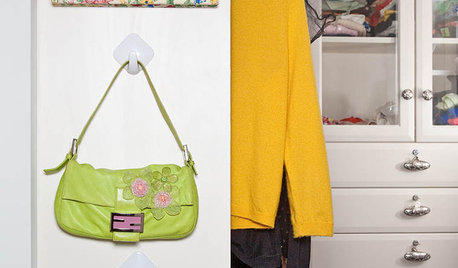
STORAGEBedroom Storage: 12 Ways to Work Your Wardrobe
Instead of letting the mess in your closet overwhelm you, tackle it head on with these smart and simple solutions
Full Story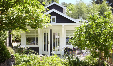
BACKYARD STUDIOS12 Garden Sheds and Cottages We Love Now
Get inspiration from these inviting backyard spaces that house offices, guest quarters, garden storage and more
Full Story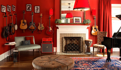
DECORATING GUIDESSpare Room? Lucky You. Here are 12 Fresh Ways to Use It
Imagine all the things you could do in your extra space: painting, planting, playing or nothing at all
Full Story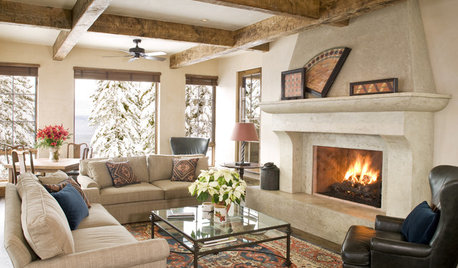
DECORATING GUIDES12 Ways to Work With Rugs for Warmth and Beauty
Try these ideas for rug placement, style and size for a pulled-together look and a great feel underfoot
Full StoryMore Discussions

javan
shastadaisy
Related Professionals
New Bedford Landscape Architects & Landscape Designers · Jennings Landscape Architects & Landscape Designers · Kyle Landscape Architects & Landscape Designers · Norton Shores Landscape Architects & Landscape Designers · Rossville Landscape Architects & Landscape Designers · Walnut Landscape Architects & Landscape Designers · Cicero Landscape Contractors · Fridley Landscape Contractors · Harrisburg Landscape Contractors · Las Vegas Landscape Contractors · Little Ferry Landscape Contractors · North Highlands Landscape Contractors · Fort Lee Solar Energy Systems · Palo Alto Solar Energy Systems · Wakefield Solar Energy SystemsoraylawsonOriginal Author
don_wilson
oraylawsonOriginal Author
gato_gordo
oraylawsonOriginal Author
don_wilson
oraylawsonOriginal Author
oraylawsonOriginal Author
greginshasta
oraylawsonOriginal Author
oranjelo
tools_r_us
oraylawsonOriginal Author
greginshasta
greginshasta
greginshasta
oraylawsonOriginal Author
milwdave
greginshasta
greginshasta
bevs_garden
oraylawsonOriginal Author
oraylawsonOriginal Author
bevs_garden
oraylawsonOriginal Author
greginshasta
greginshasta
gato_gordo
oraylawsonOriginal Author
greginshasta
oraylawsonOriginal Author
oraylawsonOriginal Author
gardenerwantabe
greginshasta
oraylawsonOriginal Author
Miss_Mudcat
oraylawsonOriginal Author
annazone5
dbw7
ChoctawWoman
funnylady
tmc2009