


Older Cub Cadet. Cannot find the voltage regulator
baymee
10 years ago
Related Stories

REMODELING GUIDESBathroom Workbook: How Much Does a Bathroom Remodel Cost?
Learn what features to expect for $3,000 to $100,000-plus, to help you plan your bathroom remodel
Full Story
LIFECondo, Co-op, Townhouse, TIC — What's the Difference?
Learn the details about housing alternatives so you can make a smart choice when buying a home
Full Story
LIGHTINGWhat to Know About Switching to LED Lightbulbs
If you’ve been thinking about changing over to LEDs but aren't sure how to do it and which to buy, this story is for you
Full Story
LIGHTING5 Questions to Ask for the Best Room Lighting
Get your overhead, task and accent lighting right for decorative beauty, less eyestrain and a focus exactly where you want
Full Story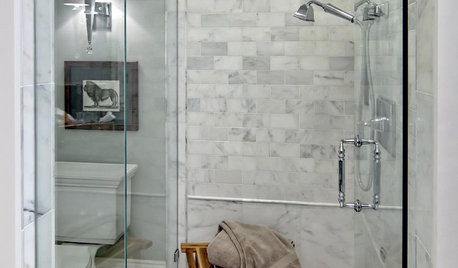
BATHROOM DESIGNHow to Settle on a Shower Bench
We help a Houzz user ask all the right questions for designing a stylish, practical and safe shower bench
Full Story
WINDOWSHow to Ditch the Drapes and Let Your Windows Shine
If your home has beautiful windows and you don’t need to hide a view, consider dressing them in these elegant, creative ways
Full Story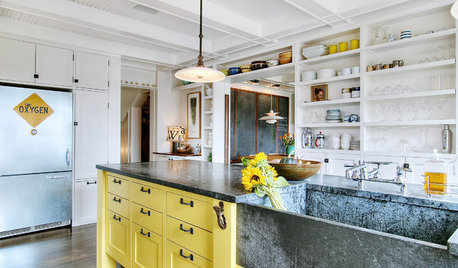
KITCHEN DESIGN10 Inventive Ideas for Kitchen Islands
Printed glass, intriguing antiques, unexpected angles – these islands show there's no end to creative options in kitchen design
Full Story
rcbe
bill_kapaun
Related Professionals
Tempe Landscape Architects & Landscape Designers · Lake Oswego Landscape Architects & Landscape Designers · Seabrook Landscape Architects & Landscape Designers · Elgin Landscape Contractors · El Mirage Landscape Contractors · Hawaii Landscape Contractors · Hilton Head Island Landscape Contractors · New Braunfels Landscape Contractors · Plymouth Landscape Contractors · Saint George Landscape Contractors · Westchester Landscape Contractors · Eastlake Landscape Contractors · Hawaiian Gardens Landscape Contractors · Auburn Window Contractors · Baltimore Window ContractorsbaymeeOriginal Author
baymeeOriginal Author
baymeeOriginal Author
bill_kapaun
baymeeOriginal Author
rcbe
mownie
bill_kapaun
baymeeOriginal Author
User
baymeeOriginal Author
mownie
mownie
User
baymeeOriginal Author
User
baymeeOriginal Author
mownie
baymeeOriginal Author
civi