


Walt Conner - B & S head gasket help
happy123
14 years ago
Related Stories
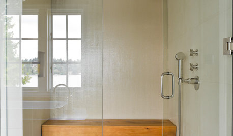
BATHROOM DESIGNOutfit Your Shower With the Right Bench for You
Whether you want a simple perch or a massive seat in your shower, our guide can help
Full Story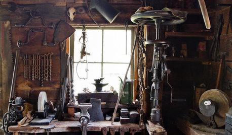
MATERIALSAre You a Maker? Show Us Your Favorite Tool or Material
Houzz Call: A tool or material can be a maker’s best friend. We’d like to see your favorite — and what it helps you achieve
Full Story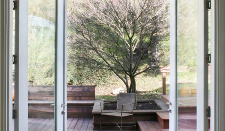
MOST POPULARFind the Right Glass Door for Your Patio
It’s more than just a patio door — it’s an architectural design element. Here’s help for finding the right one for your home and lifestyle
Full Story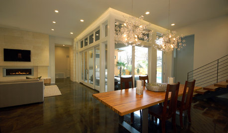
REMODELING GUIDES15 Ways to Design an Easy-Clean Home
Spend more time doing what you love with these pointers for minimizing cleaning needs throughout the entire house
Full Story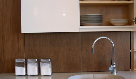
KITCHEN WORKBOOK8 Kitchen Amenities You'll Really Wish You Had
Keep kitchen mayhem and muck to a minimum with these terrific organizers and other time-saving, mess-preventing features
Full Story
REMODELING GUIDESOne Guy Found a $175,000 Comic in His Wall. What Has Your Home Hidden?
Have you found a treasure, large or small, when remodeling your house? We want to see it!
Full Story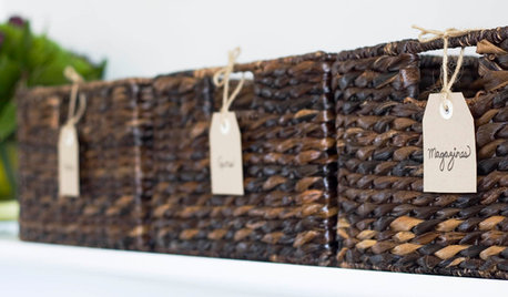
ORGANIZINGGet Organized: Are You a Piler or a Filer?
Tote out the bins and baskets and learn how to be an organized piler if file cabinets leave you cringing
Full Story
FEEL-GOOD HOME12 Very Useful Things I've Learned From Designers
These simple ideas can make life at home more efficient and enjoyable
Full Story
BATHROOM DESIGNConvert Your Tub Space Into a Shower — Waterproofing and Drainage
Step 4 in swapping your tub for a sleek new shower: Pick your waterproofing materials and drain, and don't forget to test
Full Story
ARCHITECTUREHow to Design a Storybook Cottage
A client’s request: “Build me a house where Disney meets Tudor.” The architect explores the details that make the style
Full Story
mownie
happy123Original Author
Related Professionals
New Bedford Landscape Architects & Landscape Designers · Fitchburg Landscape Architects & Landscape Designers · Ashburn Landscape Contractors · Fair Lawn Landscape Contractors · Hawthorne Landscape Contractors · Plainview Landscape Contractors · Ramsey Landscape Contractors · Vineyard Landscape Contractors · West Palm Beach Landscape Contractors · Reisterstown Landscape Contractors · Vadnais Heights Landscape Contractors · Castro Valley Window Contractors · Bridgeport Window Contractors · Coral Shores Window Contractors · Verona Window Contractorsmownie
happy123Original Author
mownie
happy123Original Author
mownie
happy123Original Author
mownie
bushleague
happy123Original Author
mownie
happy123Original Author
mownie
happy123Original Author
mownie
happy123Original Author
mownie
wheelhorse_of_course
happy123Original Author
happy123Original Author
mownie
mownie
happy123Original Author
happy123Original Author
happy123Original Author
mownie
happy123Original Author
happy123Original Author
wheelhorse_of_course
plane
mssurveyor
mownie
wadeconway
mownie
wadeconway
mownie
wadeconway
mownie
wadeconway
mownie
wadeconway
mownie
rustyj14
wadeconway
wadeconway
ewalk
fish40037
wadeconway
DIY Guy