


Snapper Rear Engine Mower Wiring
Joe3211
10 years ago

Related Stories
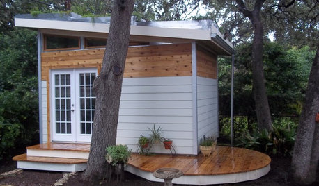
MOST POPULARHow to Add a Backyard Shed for Storage or Living
Need a home office, a playspace or extra room for your stuff? Learn about off-the-shelf, prefab and custom sheds
Full Story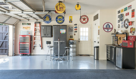
HOUSEKEEPING7-Day Plan: Get a Spotless, Beautifully Organized Garage
Stop fearing that dirty dumping ground and start using it as the streamlined garage you’ve been wanting
Full Story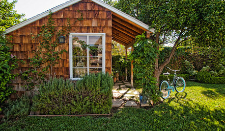
BACKYARD IDEAS7 Backyard Sheds Built With Love
The Hardworking Home: Says one homeowner and shed builder, ‘I am amazed at the peace and joy I feel when working in my garden shed’
Full Story
mownie
mownie
Related Professionals
Danbury Landscape Architects & Landscape Designers · Maple Valley Landscape Architects & Landscape Designers · Birmingham Landscape Architects & Landscape Designers · Belvedere Park Landscape Contractors · Brookfield Landscape Contractors · Centereach Landscape Contractors · Harrisburg Landscape Contractors · Vashon Landscape Contractors · Goldenrod Landscape Contractors · Raytown Landscape Contractors · Bensenville Landscape Contractors · Fort Myers Window Contractors · Richmond Window Contractors · Annapolis Window Contractors · Tamalpais-Homestead Valley Window ContractorsJoe3211Original Author
mownie
Joe3211Original Author
bill_kapaun
mownie
Joe3211Original Author
Wholly Man
Wholly Man
GR Gomez