


Best way to lock engine on a Craftsman LT1000
cjharris02892
13 years ago
Related Stories

REMODELING GUIDESWhen to Use Engineered Wood Floors
See why an engineered wood floor could be your best choice (and no one will know but you)
Full Story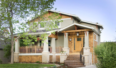
CRAFTSMAN DESIGNAmerican Architecture: The Elements of Craftsman Style
Proud of its handiwork details and with nature as inspiration, Craftsman architecture stands out for its purity of style
Full Story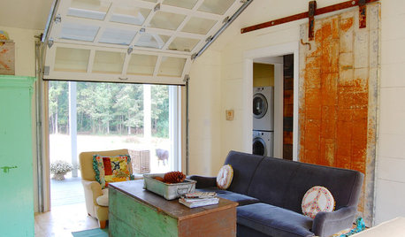
DOORSCreative Ways With Barn-Style Doors
Considering jumping on the barn-door bandwagon? These examples in different styles offer inspiration aplenty
Full Story
REMODELING GUIDES5 Ways DIY Remodels Get Derailed — and How to Deal
Keep your remodel on track by knowing the potential pitfalls ahead of time
Full Story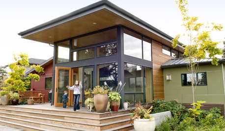
SELLING YOUR HOUSE10 Ways to Boost Your Home's Resale Value
Figure out which renovations will pay off, and you'll have more money in your pocket when that 'Sold' sign is hung
Full Story
DECORATING GUIDES6 Cost-Effective Ways to Go Custom Made
Get a look that’s totally you — and possibly for a lower cost than you might think
Full Story
KITCHEN CABINETS9 Ways to Save Money on Kitchen Cabinets
Hold on to more dough without sacrificing style with these cost-saving tips
Full Story
CRAFTSMAN DESIGNMy Houzz: Small-Space Living in a Restored Bungalow
See how this homeowner celebrates his personal style, his flea market finds and the heritage of his 1919 Long Beach home
Full Story
MOST POPULAR10 Things to Ask Your Contractor Before You Start Your Project
Ask these questions before signing with a contractor for better communication and fewer surprises along the way
Full Story
SMALL KITCHENSPersonal Spaces: Small-Kitchen Designs
In these kitchens, homeowners have found inventive ways to make the most of tight quarters
Full Story
mownie
cjharris02892Original Author
Related Professionals
Londonderry Landscape Architects & Landscape Designers · Beavercreek Landscape Architects & Landscape Designers · Birmingham Landscape Architects & Landscape Designers · Panama City Landscape Architects & Landscape Designers · Berwyn Landscape Contractors · Manhattan Landscape Contractors · Newnan Landscape Contractors · Seminole Landscape Contractors · Vallejo Landscape Contractors · Shafter Landscape Contractors · Fort Collins Window Contractors · West Chester Window Contractors · Farragut Window Contractors · Hesperia Window Contractors · Watsonville Window Contractorstomplum
mownie
rcmoser
cjharris02892Original Author
mownie
cjharris02892Original Author
cjharris02892Original Author
mownie
cjharris02892Original Author
mownie
cjharris02892Original Author
mownie
cjharris02892Original Author
cjharris02892Original Author
mownie
cjharris02892Original Author
cjharris02892Original Author
cjharris02892Original Author
mownie