


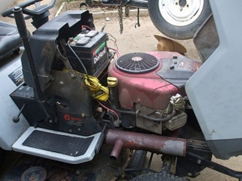
Sears GT6000 electrical questions
louky
10 years ago
Related Stories
REMODELING GUIDESConsidering a Fixer-Upper? 15 Questions to Ask First
Learn about the hidden costs and treasures of older homes to avoid budget surprises and accidentally tossing valuable features
Full Story
ACCESSORIESEasy Green: Cut Electricity Use With 15 Unplugged Home Devices
Crank up the energy savings, courtesy of household items that come into power the old-fashioned way: manually
Full Story
GREEN BUILDINGGoing Solar at Home: Solar Panel Basics
Save money on electricity and reduce your carbon footprint by installing photovoltaic panels. This guide will help you get started
Full Story
KITCHEN DESIGNA Cook’s 6 Tips for Buying Kitchen Appliances
An avid home chef answers tricky questions about choosing the right oven, stovetop, vent hood and more
Full Story
KITCHEN APPLIANCESFind the Right Cooktop for Your Kitchen
For a kitchen setup with sizzle, deciding between gas and electric is only the first hurdle. This guide can help
Full Story
LIVING ROOMSHow to Convert Your Wood-Burning Fireplace
Learn about inserts and other options for switching your fireplace from wood to gas or electric
Full Story
LIFEHow to Prepare for and Live With a Power Outage
When electricity loss puts food, water and heat in jeopardy, don't be in the dark about how to stay as safe and comfortable as possible
Full Story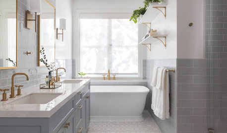
FLOORSWhat to Ask When Considering Heated Floors
These questions can help you decide if radiant floor heating is right for you — and what your options are
Full Story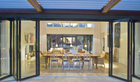
ARCHITECTURE10 Things to Know About Prefab Homes
Are prefab homes less costly, faster to build and greener than homes constructed onsite? Here are answers to those questions and more
Full Story
LIFEHow to Navigate an Extended Guest Stay
Keep sharing living quarters a positive experience by pondering the answers to these questions in advance
Full StorySponsored
mownie
bill_kapaun
Related Professionals
Fitchburg Landscape Architects & Landscape Designers · North New Hyde Park Landscape Architects & Landscape Designers · Battle Ground Landscape Contractors · East Hanover Landscape Contractors · Methuen Landscape Contractors · North Plainfield Landscape Contractors · Rockland Landscape Contractors · San Bruno Landscape Contractors · Golden Valley Landscape Contractors · Baileys Crossroads Window Contractors · Deltona Window Contractors · Glen Burnie Window Contractors · Hesperia Window Contractors · Meridian Window Contractors · Woodland Hills Window ContractorsloukyOriginal Author
mownie
bill_kapaun
loukyOriginal Author
bill_kapaun
mownie
loukyOriginal Author
mownie
loukyOriginal Author
bill_kapaun
loukyOriginal Author
loukyOriginal Author
bill_kapaun
mownie
loukyOriginal Author
bill_kapaun
loukyOriginal Author
bill_kapaun
loukyOriginal Author
bill_kapaun
loukyOriginal Author
loukyOriginal Author
bill_kapaun