


B&S 14.5 HP flywheel magnets
funflyer54
14 years ago
Related Stories

BATHROOM DESIGNShower Curtain or Shower Door?
Find out which option is the ideal partner for your shower-bath combo
Full Story
GREEN BUILDINGThe Big Freeze: Inventors Break New Ground to Keep Things Cool
Old-fashioned fridges can be energy guzzlers, but there are more eco-friendly ways of keeping food fresh, as these global innovations show
Full Story
HOUZZ TOURSMy Houzz: Neutral and Natural Elegance in Texas
Creamy hues, plush furnishings and vintage touches create a serene setting for a stylist and her family
Full Story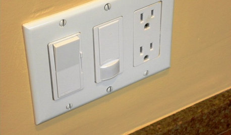
GREAT HOME PROJECTSHow to Install a Dimmer Switch
New project for a new year: Take control of your lighting to set the right mood for entertaining, dining and work
Full Story
KITCHEN DESIGNShow Us Your Fabulous DIY Kitchen
Did you do a great job when you did it yourself? We want to see and hear about it
Full Story
REMODELING GUIDESHome Elevators: A Rising Trend
The increasing popularity of aging in place and universal design are giving home elevators a boost, spurring innovation and lower cost
Full Story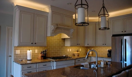
LIGHTINGThe Lowdown on High-Efficiency LED Lighting
Learn about LED tapes, ropes, pucks and more to create a flexible and energy-efficient lighting design that looks great
Full Story
KITCHEN STORAGEKnife Shopping and Storage: Advice From a Kitchen Pro
Get your kitchen holiday ready by choosing the right knives and storing them safely and efficiently
Full Story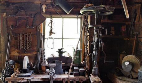
MATERIALSAre You a Maker? Show Us Your Favorite Tool or Material
Houzz Call: A tool or material can be a maker’s best friend. We’d like to see your favorite — and what it helps you achieve
Full Story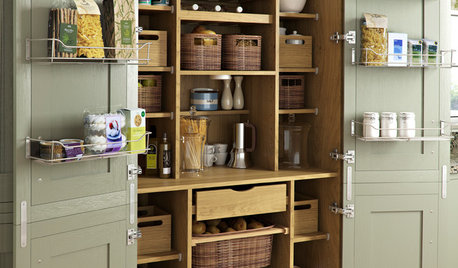
KITCHEN PANTRIES80 Pretty and Practical Kitchen Pantries
This collection of kitchen pantries covers a wide range of sizes, styles and budgets
Full Story
markymark-ca
mownie
Related Professionals
Elwood Landscape Architects & Landscape Designers · River Forest Landscape Architects & Landscape Designers · Seabrook Landscape Architects & Landscape Designers · Simi Valley Landscape Architects & Landscape Designers · Concord Landscape Contractors · Damascus Landscape Contractors · Deerfield Landscape Contractors · Indio Landscape Contractors · Lemay Landscape Contractors · Lemoore Landscape Contractors · Thornton Landscape Contractors · Dalton Window Contractors · Indian Creek Window Contractors · Spanaway Window Contractors · Cheshire Gardeners & Lawn Carefunflyer54Original Author
rustyj14
walt2002
mownie
rustyj14
mownie
larso1
walt2002
walt2002
hankll
mownie
walt2002
mownie
walt2002
rustyj14
rcmoser
tjukuk