


Craftsman tractor - B&S sudden failure
MikeK1005
10 years ago
Related Stories

KITCHEN CABINETSKitchen Cabinet Color: Should You Paint or Stain?
Learn about durability, looks, cost and more for wooden cabinet finishes to make the right choice for your kitchen
Full Story
LIFERetirement Reinvention: Boomers Plot Their Next Big Move
Choosing a place to settle in for the golden years? You're not alone. Where boomers are going and what it might look like
Full Story
BATHROOM DESIGN5 Common Bathroom Design Mistakes to Avoid
Get your bath right for the long haul by dodging these blunders in toilet placement, shower type and more
Full Story
DECORATING GUIDESFrom Queasy Colors to Killer Tables: Your Worst Decorating Mistakes
Houzzers spill the beans about buying blunders, painting problems and DIY disasters
Full Story
REMODELING GUIDES8 Lessons on Renovating a House from Someone Who's Living It
So you think DIY remodeling is going to be fun? Here is one homeowner's list of what you may be getting yourself into
Full Story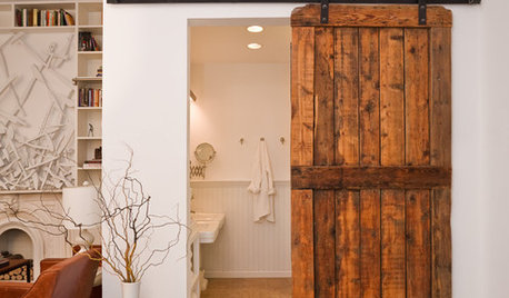
DOORS5 Questions to Ask Before Installing a Barn Door
Find out whether that barn door you love is the right solution for your space
Full Story
DECLUTTERING10 Decluttering Projects You Can Do in 15 Minutes or Less
Try these ideas to get organized at home one small step at a time
Full Story
KITCHEN CABINETSPainted vs. Stained Kitchen Cabinets
Wondering whether to go for natural wood or a painted finish for your cabinets? These pros and cons can help
Full Story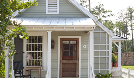
SMALL SPACES8 Benefits of Cottage Living
Scale back to dial up your quality of life, save money and more
Full Story
MOST POPULARDesign Debate: Is It OK to Hang the TV Over the Fireplace?
In the spirit of the upcoming political debates, we kick off a series of conversations on hotly contested design topics
Full Story
fearboy
tomplum
Related Professionals
Windham Landscape Architects & Landscape Designers · Wheeling Landscape Architects & Landscape Designers · Clermont Landscape Contractors · Englewood Landscape Contractors · Flagstaff Landscape Contractors · Fort Mill Landscape Contractors · Galt Landscape Contractors · Parker Landscape Contractors · 07920 Landscape Contractors · Shafter Landscape Contractors · Houston Window Contractors · San Jose Window Contractors · DeLand Window Contractors · Holly Hill Window Contractors · Manville Window ContractorsMikeK1005Original Author
mownie
MikeK1005Original Author
MikeK1005Original Author
tomplum
mownie
tomplum
fearboy
mownie